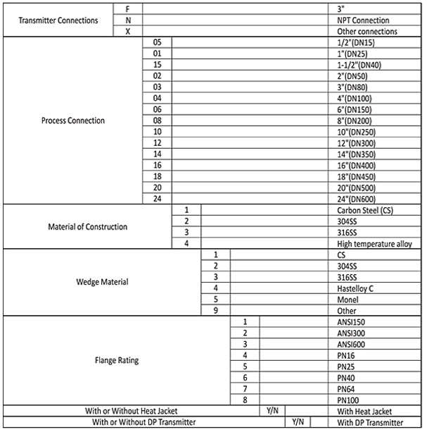
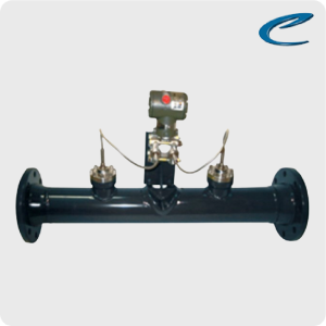
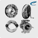
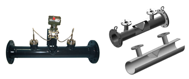
HWM Series Wedge Flow Meter is an flow gauge (meter) that measure quantity of flow in poor conditions. HWM Series can be measure to quantity of flow like as Liquid, Gas, Steam, as well as fluid included sludge. Specially, it is suitable to measure quantity of flow for flow fluid with high viscosity.
It is possible to measure both flow.
SPECIFICATION
FEATURES
– Measure Liquids, Gas and Steam
– Bi-directional flow
-Low Reynolds number (<300)
– Minimum upstream and downstream requirements
– Standard sizes 0.5″ to 24″ (15DN600 mm)
-High temperature application with remote mount DP transmitter
FLOW BODY
-Line size: DN15DN600 mm
– Accuracy (calibrated) : 1%, 0.5% ; ( un-calibrated): 3%
-Turn down ratio up to 10:1
– Working pressure up to 42.0MPa
– Operating temperature up to 400
– Transmitter Connections 3 in. RF flange (SCH 80 I.D.)
– Process connection ANSI and DIN
– Body material: cast Iron, stainless steel, high temperature alloy. -Wedge: Stainless steel, Monel, Hastelloy C, high temperature alloy. – Repeatability 0.2%
GENERAL
Hitelfi Wedge Flow Meter (HWM)
Hitelfi Differential Pressure Wedge Meters represents one of the many DP flow technologies available in our program. Hitelfi meters consist of a flow body with (see below) wedge “V” shape throttle restriction. This restriction creates a differential pressure between ((P1) before and (P2) after the wedge (P2))-see below which is proportion to the square of the volumetric flow rate. The wedge restriction has no critical surface dimensions, or sharp edges, that will affect measurement accuracy as the result of normally expected wear. Hitelfi meter is excellent for very low flows or low Reynolds number (Re. < 500), high-viscosity fluids which contains dust or solid particle or applications such as liquid cement, crude oil coal-tar oil, wastewater, hard pulp, asphaltic oil, coal-tar oil, wastewater, hard pulp, carbon black solution, two phase flows, etc.
FLOW CALCULATION THEORY
The line fluid is forced downward similar to a segmental orifice plate, but is guided along a sloping “wedge” shape rather than a sharp edge. The pressure taps are located upstream and downstream of the wedge and in all cases are equipped with Sealed Sensors. The differential produced by the device is a function of the ratio between the wedge segment opening, H, and the diameter of the body, D.
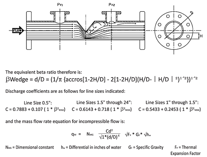
The calculations for compressible flow are similar but must account for temperature and Adiabatic Expansion and Compressibility factors.
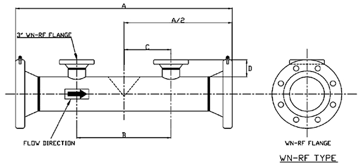
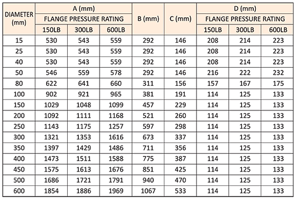
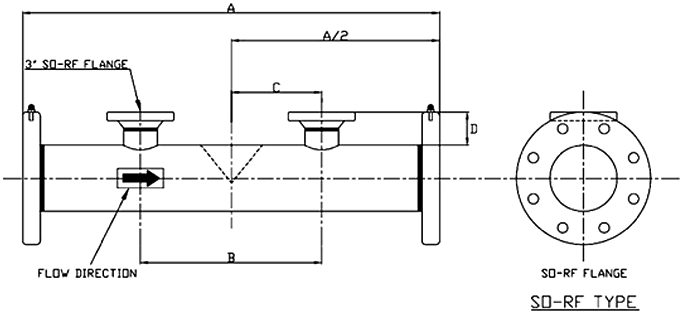
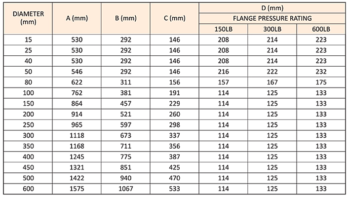
MODEL (HWM)
Type of liquid: We need the name of your liquid, including operating density and viscosity
Full Scale Flow: We need your maximum and minimum flow rates, units must be Kg/hr, Lb/hr, LPM or gpm, etc..
Line Size: We need to know your pipe size as well connection type (flange, threaded, etc..)
Process Pressure and Temperature: We calibration your mass flow meter as close to your application as possible
Pressure drop: Please indicated the maximum pressure drop (see graph below) that your process can withstand
Type of Electronics: Indicate if you want integral, remote panel or remote wall mounted.
MODEL SELECTION GUIDE
HWM Series
